GaN can put more RF power into a smaller radar module. Whether that becomes sustained radar performance depends on the entire heat path, from the transistor channel to the platform's cooling system.
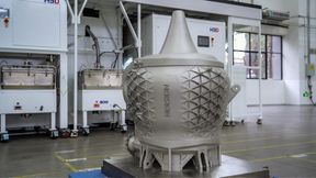
RF output and heat rejection share the same module. Conceptual illustration of a radar array and its thermal path; not a product photograph.
(Source: KI-generiert / Imagen)
A transistor record is not an array rating
Gallium nitride has expanded the power available to radar designers. Its wide bandgap and high breakdown capability support RF power densities that make compact, high-output amplifiers possible. Compared with gallium arsenide, it gives the transmitter a different set of voltage and power-density options. GaAs remains useful in RF systems, including receive functions; replacing a semiconductor is not itself a radar architecture.
The gain in watts per millimetre also concentrates dissipation near the transistor's active region. More RF output can improve a radar's available signal energy, but only while the amplifier maintains the required output and the array can reject the resulting heat. Once the channel temperature reaches the design limit, the system must reduce power, duty cycle or operating time. The limiting specification then moves from a transistor data sheet to the cooling chain.
Two recent results show why this matters. In June 2026, DARPA reported that the first phase of its THREADS programme achieved roughly five times the RF power density of the state of the art while maintaining defence-relevant lifetime targets. The programme addresses thermal barriers and is continuing into further development. This is an enabling-device result, not a statement that an installed radar now delivers five times its previous power.
On 22 September, Qorvo reported more than a 400 per cent increase in RF power density for an X-band GaN transistor developed under THREADS. That is the company's reported comparison for the device. It must not be converted directly into an array-level output, detection range or fleet availability claim. Packaging, operating waveform, electrical supply and heat rejection remain between the laboratory result and the radar mission.
Heat begins in the channel
The useful starting point is the hottest relevant transistor region, rather than the temperature of the module's outer surface. A cool-looking case can coexist with a much hotter channel if the path between them has high thermal resistance. Conversely, thermal resistance alone does not determine reliability: dissipated power and the temperature at the other end of the path also matter.
For an amplifier, dissipated heat is the electrical input plus RF input minus RF output. Neglecting a small RF drive input, a hypothetical amplifier delivering 100 watts at 50 per cent drain efficiency draws 200 watts from its supply and dissipates about 100 watts. These are illustrative values, not the specification of a particular radar device. Better efficiency reduces the cooling burden for a given RF output.
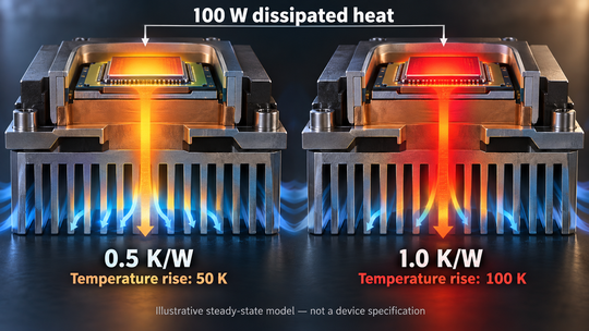
Under steady conditions, a first approximation is ΔT = PdissRθ. A 100-watt heat load across a hypothetical 0.5 kelvin-per-watt path produces a 50-kelvin temperature rise. Doubling that path's resistance doubles the rise in this simplified example. The temperature of the heat sink must then be added. Neither a good heat sink nor an efficient transistor can compensate indefinitely for a poor interface between them.
Every interface has a role
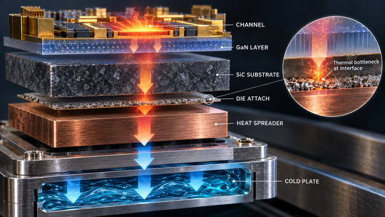
Heat leaves the active region through a stack of materials and interfaces: the semiconductor structure, substrate, die attach, package or carrier, module base and cooling assembly. Silicon carbide is widely used as a GaN substrate because its properties support demanding RF applications. Other heat-spreading approaches, including diamond, seek to reduce local temperature rise. The installed result depends on how the materials are joined and where the heat must flow.
High bulk thermal conductivity is therefore only part of the answer. Boundary resistance, bond thickness, voids and mechanical flatness can dominate a short heat path. Adding a superior spreader above a poor joint may produce little improvement. Thermal expansion differences also matter when an assembly repeatedly heats and cools. The manufacturing process has to preserve both the thermal contact and the RF structure.
Date: 08.12.2025
Naturally, we always handle your personal data responsibly. Any personal data we receive from you is processed in accordance with applicable data protection legislation. For detailed information please see our privacy policy.
Consent to the use of data for promotional purposes
I hereby consent to Vogel Communications Group GmbH & Co. KG, Max-Planck-Str. 7-9, 97082 Würzburg including any affiliated companies according to §§ 15 et seq. AktG (hereafter: Vogel Communications Group) using my e-mail address to send editorial newsletters. A list of all affiliated companies can be found here
Newsletter content may include all products and services of any companies mentioned above, including for example specialist journals and books, events and fairs as well as event-related products and services, print and digital media offers and services such as additional (editorial) newsletters, raffles, lead campaigns, market research both online and offline, specialist webportals and e-learning offers. In case my personal telephone number has also been collected, it may be used for offers of aforementioned products, for services of the companies mentioned above, and market research purposes.
Additionally, my consent also includes the processing of my email address and telephone number for data matching for marketing purposes with select advertising partners such as LinkedIn, Google, and Meta. For this, Vogel Communications Group may transmit said data in hashed form to the advertising partners who then use said data to determine whether I am also a member of the mentioned advertising partner portals. Vogel Communications Group uses this feature for the purposes of re-targeting (up-selling, cross-selling, and customer loyalty), generating so-called look-alike audiences for acquisition of new customers, and as basis for exclusion for on-going advertising campaigns. Further information can be found in section “data matching for marketing purposes”.
In case I access protected data on Internet portals of Vogel Communications Group including any affiliated companies according to §§ 15 et seq. AktG, I need to provide further data in order to register for the access to such content. In return for this free access to editorial content, my data may be used in accordance with this consent for the purposes stated here. This does not apply to data matching for marketing purposes.
Right of revocation
I understand that I can revoke my consent at will. My revocation does not change the lawfulness of data processing that was conducted based on my consent leading up to my revocation. One option to declare my revocation is to use the contact form found at https://contact.vogel.de. In case I no longer wish to receive certain newsletters, I have subscribed to, I can also click on the unsubscribe link included at the end of a newsletter. Further information regarding my right of revocation and the implementation of it as well as the consequences of my revocation can be found in the data protection declaration, section editorial newsletter.
Heterogeneous integration makes these interfaces a central design task. Different materials and device technologies can be combined where they contribute most, but every added boundary needs thermal and mechanical characterisation. A compact assembly that performs well on one demonstration unit still requires a repeatable attachment process, inspection criteria and evidence on ageing. Thermal performance is a production capability as much as a materials property.
Thermal interfaces connect the transistor channel to platform cooling. A high-conductivity material cannot remove resistance elsewhere in the stack.
(Source: KI-generiert / Imagen)
Pulses require a time-dependent model
A steady thermal resistance does not describe every radar pulse. Temperature responds over several time scales as heat spreads from the channel into the package and then into the larger assembly. Transient thermal impedance and the preceding pulse train help determine the peak channel temperature. Average dissipation is essential for cooling-system sizing, but it may not reveal the peak temperature during a demanding burst.
Analog Devices' work on GaN pulse droop explains how self-heating can reduce RF output during a pulse. Electrical supply behaviour can cause droop as well, so the two mechanisms must be distinguished by measurement. A heat-related decline cannot be solved solely by making the power supply stiffer; a supply limitation cannot be diagnosed solely from a warm package.
Across an AESA aperture, local hot spots and uneven coolant distribution can restrict particular modules. Thermal scheduling may reduce demanding waveform time or simultaneous tasks before a nominal maximum-range rating changes.
Illustrative values: 100 W dissipated through 0.5 K/W gives a 50 K rise; at 1 K/W it gives 100 K. These are not device specifications.
(Source: KI-generiert / Imagen)
The title has a condition attached
For an otherwise unchanged monostatic radar and a fixed detection threshold, the familiar radar equation gives maximum range proportional to the fourth root of transmitted power. A thermal limit that forces a reduction in usable power can therefore reduce range. Temperature itself is not a term that directly and universally shortens detection distance. Antenna gain, losses, target radar cross-section, processing and the interference environment also shape the result.
The platform sets the final boundary
A module's thermal qualification is meaningful only with its stated boundary conditions. An aircraft has limits on cooling mass, available electrical power and the heat it can reject. A ship may have more substantial cooling infrastructure, but the radar still depends on a complete path to it. Ground systems face their own ambient temperatures, fouling and maintenance conditions. None can be represented by an indefinitely cold laboratory plate.
This is why sustained performance should be specified at the platform interface. The requirement needs inlet or sink temperature, coolant conditions where relevant, duty cycle and operating duration. It should also define degraded operation if cooling capacity falls. A supplier can otherwise deliver a compliant module that the integrator cannot operate at its advertised output in the intended installation.
Lifetime creates a further trade. Channel temperature influences device reliability, but the relationship depends on the technology and failure mechanism. A universal rule assigning the same lifetime penalty to each temperature increment would be misleading. Qualification needs the relevant process data, thermal cycling and mission profile rather than a single headline maximum temperature.
For suppliers, this shifts value towards repeatable die attachment, heat-spreader integration, module assembly and thermal metrology. For integrators, it raises the importance of measurements that connect an RF operating point to channel temperature and platform heat load. The next radar procurement should ask how much output is sustainable under specified conditions, and what evidence supports that claim. A transistor can offer more power than a radar can use; a well-engineered heat path makes the difference.